Half adder and full adder circuit, design and implementation
Half Adder
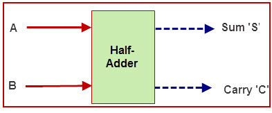
The addition of 2bits is called Half adder the input variebles are augent and addent bits and output variebles are sum&carry bits. A and B are the two input bits
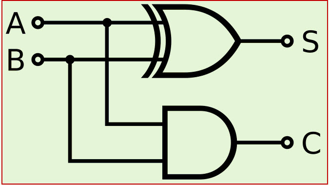
There are two inputs and two outputs in a Half Adder. Inputs are named as A and B, and the outputs are named as Sum (S) and Carry (C). The Sum is X-OR of the input A and B. Carry is AND of the input A and B. With the help of half adder, one can design a circuit that is capable of performing simple addition with the help of logic gates. Let us first take a look at the addition of single bits.
Logical Expression
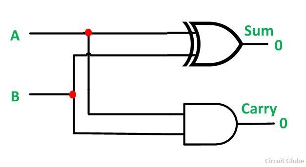
Sum = A XOR B Carry = A AND B
Half AdderHalf Adder Logic Circuit
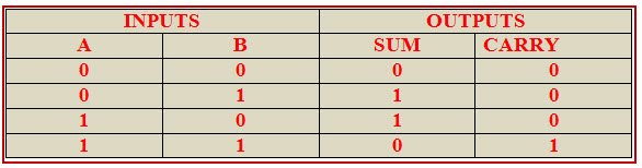
Half Adder Truth Table
Full Adder in Digital Logic
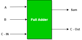
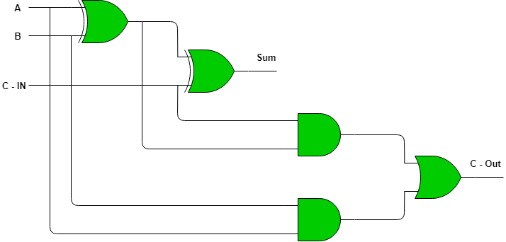
Full Adder is the adder which adds three inputs and produces two outputs. The first two inputs are A and B and the third input is an input carry as C-IN. The output carry is designated as C-OUT and the normal output is designated as S which is SUM.
A full adder logic is designed in such a manner that can take eight inputs together to create a byte-wide adder and cascade the carry bit from one adder to the another.
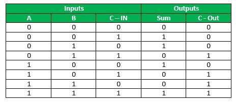
Full Adder Truth Table:
Full Adder logic circuit.
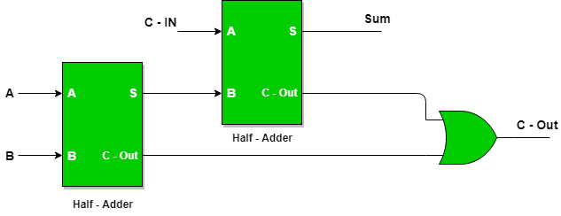
Implementation of Full Adder using Half Adders
2 Half Adders and a OR gate is required to implement a Full Adder.
With this logic circuit, two bits can be added together, taking a carry from the next lower order of magnitude, and sending a carry to the next higher order of magnitude.
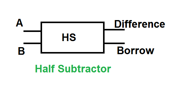
Half Subtractor in Digital Logic
It is a combinational circuit that performs subtraction of two binary bits. It has two inputs (minuend and subtrahend) and two outputs Difference (D) and Borrows (Bout). We use half-subtractor to subtract the LSB of the subtrahend to the LSB of the minuend when one binary number is subtracted from another.
Half subtractor is the most essential combinational logic circuit which is used in digital electronics. Basically, this is an electronic device or in other terms, we can say it as a logic circuit. Half subtractor is used to perform two binary digits subtraction. In the previous article, we have already discussed the concepts of half adder and a full adder circuit which uses the binary numbers for the calculation.
Half Subtractor ( HS )
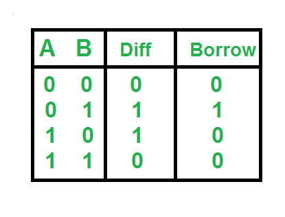
Truth Table
Logical Expression
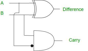
Difference = A XOR B
Borrow =
Implementation
Application of Half Subtractor
The applications of half subtractor include the following.
Half subtractor is used to reduce the force of audio or radio signals
It can be used to increase and decrease operators and also calculates the addresses
Half subtractor is used to subtract the least significant column numbers. For subtraction of multi-digit numbers, it can be used for the LSB.
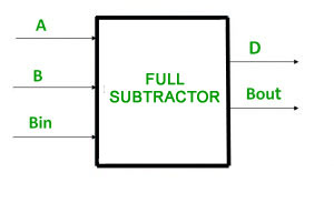
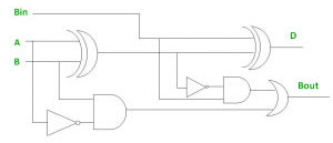
Full Subtractor in Digital Logic
A full subtractor is a combinational circuit that performs subtraction of two bits, one is minuend and other is subtrahend, taking into account borrow of the previous adjacent lower minuend bit. This circuit has three inputs and two outputs. The three inputs A, B and Bin, denote the minuend, subtrahend, and previous borrow, respectively. The two outputs, D and Bout represent the difference and output borrow, respectively.
Full Subtractor also belongs to the class of a combinational circuit and is used to perform subtraction of two binary bits. The half-subtractor can only be used for subtraction of LSB bits, but if there occurs a case of borrow during subtraction of LSB bits, then it can have affected over subtraction in higher columns
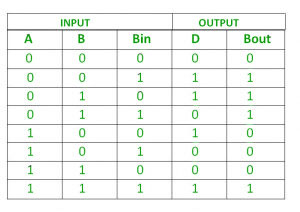
Truth Table –
From above table we can draw the K-Map as shown for “difference” and “borrow”.
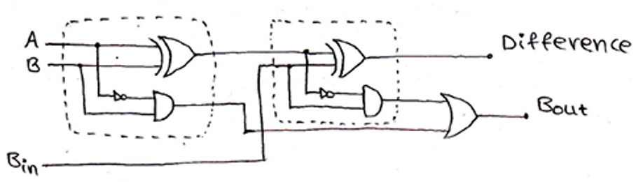
Logic Circuit for Full Subtractor –
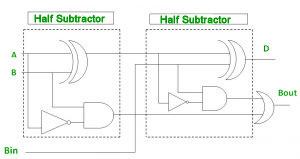
Implementation of Full Subtractor using Half Subtractors –
2 Half Subtractors and an OR gate is required to implement a Full Subtractor.
Designing of Full Subtractor using Half-Subtractors
A Full-Subtractor can also be implemented using two half-subtractors and one OR gate. The circuit diagram for this can be drawn as,


No comments:
Post a Comment