
Logic Gates –
Digital electronic circuits operate with voltages of two logic levelsnamely Logic Low and Logic High. The range of voltages corresponding to Logic Low is represented with ‘0’. Similarly, the range of voltages corresponding to Logic High is represented with ‘1’.
The basic digital electronic circuit that has one or more inputs and single output is known as Logic gate. Hence, the Logic gates are the building blocks of any digital system. We can classify these Logic gates into the following three categories.
- Basic gates
- Universal gates
- Special gates
Now, let us discuss about the Logic gates come under each category one by one.
Basic Gates
In earlier chapters, we learnt that the Boolean functions can be represented either in sum of products form or in product of sums form based on the requirement. So, we can implement these Boolean functions by using basic gates. The basic gates are AND, OR & NOT gates.
AND gate
An AND gate is a digital circuit that has two or more inputs and produces an output, which is the logical AND of all those inputs. It is optional to represent the Logical AND with the symbol ‘.’.
The following table shows the truth tableof 2-input AND gate.
| A | B | Y = A.B |
|---|---|---|
| 0 | 0 | 0 |
| 0 | 1 | 0 |
| 1 | 0 | 0 |
| 1 | 1 | 1 |
Here A, B are the inputs and Y is the output of two input AND gate. If both inputs are ‘1’, then only the output, Y is ‘1’. For remaining combinations of inputs, the output, Y is ‘0’.
The following figure shows the symbol of an AND gate, which is having two inputs A, B and one output, Y.

This AND gate produces an output , which is the logical AND of two inputs A, B. Similarly, if there are ‘n’ inputs, then the AND gate produces an output, which is the logical AND of all those inputs. That means, the output of AND gate will be ‘1’, when all the inputs are ‘1’.
AND gate(.) – The AND gate gives an output of 1 if both the two inputs are 1, it gives 0 otherwise
OR gate
An OR gate is a digital circuit that has two or more inputs and produces an output, which is the logical OR of all those inputs. This logical OR is represented with the symbol ‘+’.
The following table shows the truth tableof 2-input OR gate.
| A | B | Y = A + B |
|---|---|---|
| 0 | 0 | 0 |
| 0 | 1 | 1 |
| 1 | 0 | 1 |
| 1 | 1 | 1 |
Here A, B are the inputs and Y is the output of two input OR gate. If both inputs are ‘0’, then only the output, Y is ‘0’. For remaining combinations of inputs, the output, Y is ‘1’.
The following figure shows the symbol of an OR gate, which is having two inputs A, B and one output, Y.

This OR gate produces an output , which is the logical OR of two inputs A, B. Similarly, if there are ‘n’ inputs, then the OR gate produces an output, which is the logical OR of all those inputs. That means, the output of an OR gate will be ‘1’, when at least one of those inputs is ‘1’.
OR gate(+) – The OR gate gives an output of 1 if either of the two inputs are 1, it gives 0 otherwise
NOT gate
A NOT gate is a digital circuit that has single input and single output. The output of NOT gate is the logical inversion of input. Hence, the NOT gate is also called as inverter.
Th following table shows the truth tableof
NOT gate.
| A | Y = A’ |
|---|---|
| 0 | 1 |
| 1 | 0 |
Here A and Y are the input and output of NOT gate respectively. If the input, A is ‘0’, then the output, Y is ‘1’. Similarly, if the input, A is ‘1’, then the output, Y is ‘0’.
The following figure shows the symbol of NOT gate, which is having one input, A and one output, Y.

This NOT gate produces an output , which is the complement of input, A.
- NOT gate(‘) – The NOT gate gives an output of 1 input is 0 and vice-versa.
Universal gates
NAND & NOR gates are called as universal gates. Because we can implement any Boolean function, which is in sum of products form by using NAND gates alone. Similarly, we can implement any Boolean function, which is in product of sums form by using NOR gates alone.
NAND gate
NAND gate is a digital circuit that has two or more inputs and produces an output, which is the inversion of logical AND of all those inputs.
The following table shows the truth tableof 2-input NAND gate.
| A | B | Y = ’ |
|---|---|---|
| 0 | 0 | 1 |
| 0 | 1 | 1 |
| 1 | 0 | 1 |
| 1 | 1 | 0 |
Here A, B are the inputs and Y is the output of two input NAND gate. When both inputs are ‘1’, the output, Y is ‘0’. If at least one of the input is zero, then the output, Y is ‘1’. This is just opposite to that of two input AND gate operation.
The following image shows the symbol of NAND gate, which is having two inputs A, B and one output, Y.

NAND gate operation is same as that of AND gate followed by an inverter. That’s why the NAND gate symbol is represented like that.
- NAND gate()- The NAND gate (negated AND) gives an output of 0 if both inputs are 1, it gives 1 otherwise.


NOR gate
NOR gate is a digital circuit that has two or more inputs and produces an output, which is the inversion of logical OR of all those inputs.
The following table shows the truth tableof 2-input NOR gate
| A | B | Y = ’ |
|---|---|---|
| 0 | 0 | 1 |
| 0 | 1 | 0 |
| 1 | 0 | 0 |
| 1 | 1 | 0 |
Here A, B are the inputs and Y is the output. If both inputs are ‘0’, then the output, Y is ‘1’. If at least one of the input is ‘1’, then the output, Y is ‘0’. This is just opposite to that of two input OR gate operation.
The following figure shows the symbol of NOR gate, which is having two inputs A, B and one output, Y.

NOR gate operation is same as that of OR gate followed by an inverter. That’s why the NOR gate symbol is represented like that.
- NOR gate()- The NOR gate (negated OR) gives an output of 1 if both inputs are 0, it gives 1 otherwise.

Special Gates
Ex-OR & Ex-NOR gates are called as special gates. Because, these two gates are special cases of OR & NOR gates.
Ex-OR gate
The full form of Ex-OR gate is Exclusive-OR gate. Its function is same as that of OR gate except for some cases, when the inputs having even number of ones.
The following table shows the truth tableof 2-input Ex-OR gate.
| A | B | Y = A⊕B |
|---|---|---|
| 0 | 0 | 0 |
| 0 | 1 | 1 |
| 1 | 0 | 1 |
| 1 | 1 | 0 |
Here A, B are the inputs and Y is the output of two input Ex-OR gate. The truth table of Ex-OR gate is same as that of OR gate for first three rows. The only modification is in the fourth row. That means, the output is zero instead of one, when both the inputs are one, since the inputs having even number of ones.
Therefore, the output of Ex-OR gate is ‘1’, when only one of the two inputs is ‘1’. And it is zero, when both inputs are same.
Below figure shows the symbol of Ex-OR gate, which is having two inputs A, B and one output, Y.

Ex-OR gate operation is similar to that of OR gate, except for few combination of inputs. That’s why the Ex-OR gate symbol is represented like that. The output of Ex-OR gate is ‘1’, when odd number of ones present at the inputs. Hence, the output of Ex-OR gate is also called as an odd function.
- XOR gate() – The XOR gate gives an output of 1 if either both inputs are different, it gives 0 if they are same.


Ex-NOR gate
The full form of Ex-NOR gate is Exclusive-NOR gate. Its function is same as that of NOR gate except for some cases, when the inputs having even number of ones.
The following table shows the truth tableof 2-input Ex-NOR gate.
| A | B | Y = A⊙B |
|---|---|---|
| 0 | 0 | 1 |
| 0 | 1 | 0 |
| 1 | 0 | 0 |
| 1 | 1 | 1 |
Here A, B are the inputs and Y is the output. The truth table of Ex-NOR gate is same as that of NOR gate for first three rows. The only modification is in the fourth row. That means, the output is one instead of zero, when both the inputs are one.
Therefore, the output of Ex-NOR gate is ‘1’, when both inputs are same. And it is zero, when both the inputs are different.
The following figure shows the symbol of Ex-NOR gate, which is having two inputs A, B and one output, Y.

Ex-NOR gate operation is similar to that of NOR gate, except for few combinationof inputs. That’s why the Ex-NOR gate symbol is represented like that. The output of Ex-NOR gate is ‘1’, when even number of ones present at the inputs. Hence, the output of Ex-NOR gate is also called as an even function.
From the above truth tables of Ex-OR & Ex-NOR logic gates, we can easily notice that the Ex-NOR operation is just the logical inversion of Ex-OR operation.
- XNOR gate()- The XNOR gate (negated XOR) gives an output of 1 both inputs are same and 0 if both are different.

De Morgan's Theorems
DeMorgan’s Theorems are two additional simplification techniques that can be used to simplify Boolean expressions. Again, the simpler the Boolean expression the simpler the resulting the Boolean expression, the simpler the resulting logic.
De Morgan has suggested two theorems which are extremely useful in Boolean Algebra. The two theorems are discussed below.
Theorem 1
- The left hand side (LHS) of this theorem represents a NAND gate with inputs A and B, whereas the right hand side (RHS) of the theorem represents an OR gate with inverted inputs.
- This OR gate is called as Bubbled OR.
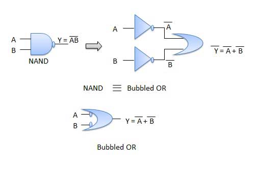
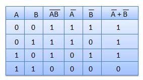
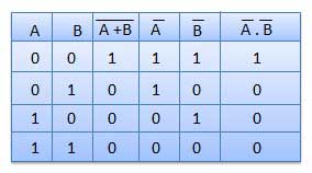
Table showing verification of the De Morgan's first theorem −
Theorem 2
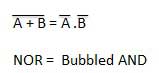
- The LHS of this theorem represents a NOR gate with inputs A and B, whereas the RHS represents an AND gate with inverted inputs.
- This AND gate is called as Bubbled AND.
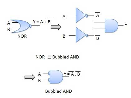
Table showing verification of the De Morgan's second theorem −
Introduction of K-Map (Karnaugh Map)
In many digital circuits and practical problems we need to find expression with minimum variables. We can minimize Boolean expressions of 3, 4 variables very easily using K-map without using any Boolean algebra theorems. K-map can take two forms Sum of Product (SOP) and Product of Sum (POS) according to the need of problem. K-map is table like representation but it gives more information than TRUTH TABLE. We fill grid of K-map with 0’s and 1’s then solve it by making groups.
Steps to solve expression using K-map-
- Select K-map according to the number of variables.
- Identify minterms or maxterms as given in problem.
- For SOP put 1’s in blocks of K-map respective to the minterms (0’s elsewhere).
- For POS put 0’s in blocks of K-map respective to the maxterms(1’s elsewhere).
- Make rectangular groups containing total terms in power of two like 2,4,8 ..(except 1) and try to cover as many elements as you can in one group.
- From the groups made in step 5 find the product terms and sum them up for SOP form.
K-Maps for 2 to 5 Variables
K-Map method is most suitable for minimizing Boolean functions of 2 variables to 5 variables. Now, let us discuss about the K-Maps for 2 to 5 variables one by one.
2 Variable K-Map
The number of cells in 2 variable K-map is four, since the number of variables is two. The following figure shows 2 variable K-Map.
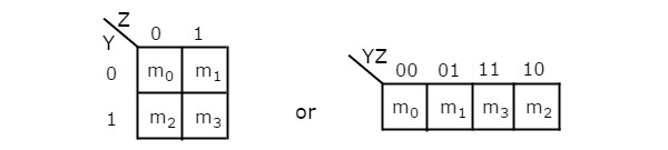
- There is only one possibility of grouping 4 adjacent min terms.
- The possible combinations of grouping 2 adjacent min terms are {(m0, m1), (m2, m3), (m0, m2) and (m1, m3)}.
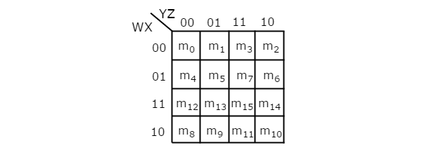
3 Variable K-Map
The number of cells in 3 variable K-map is eight, since the number of variables is three. The following figure shows 3 variable K-Map.

- There is only one possibility of grouping 8 adjacent min terms.
- The possible combinations of grouping 4 adjacent min terms are {(m0, m1, m3, m2), (m4, m5, m7, m6), (m0, m1, m4, m5), (m1, m3, m5, m7), (m3, m2, m7, m6) and (m2, m0, m6, m4)}.
- The possible combinations of grouping 2 adjacent min terms are {(m0, m1), (m1, m3), (m3, m2), (m2, m0), (m4, m5), (m5, m7), (m7, m6), (m6, m4), (m0, m4), (m1, m5), (m3, m7) and (m2, m6)}.
- If x=0, then 3 variable K-map becomes 2 variable K-map.
4 Variable K-Map
The number of cells in 4 variable K-map is sixteen, since the number of variables is four. The following figure shows 4 variable K-Map.
- There is only one possibility of grouping 16 adjacent min terms.
- Let R1, R2, R3 and R4 represents the min terms of first row, second row, third row and fourth row respectively. Similarly, C1, C2, C3 and C4 represents the min terms of first column, second column, third column and fourth column respectively. The possible combinations of grouping 8 adjacent min terms are {(R1, R2), (R2, R3), (R3, R4), (R4, R1), (C1, C2), (C2, C3), (C3, C4), (C4, C1)}.
- If w=0, then 4 variable K-map becomes 3 variable K-map.
5 Variable K-Map
The number of cells in 5 variable K-map is thirty-two, since the number of variables is 5. The following figure shows 5 variable K-Map.
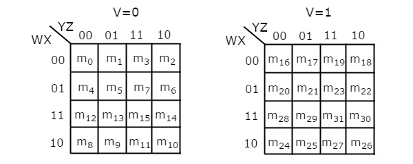
- There is only one possibility of grouping 32 adjacent min terms.
- There are two possibilities of grouping 16 adjacent min terms. i.e., grouping of min terms from m0 to m15 and m16 to m31.
- If v=0, then 5 variable K-map becomes 4 variable K-map.
In the above all K-maps, we used exclusively the min terms notation. Similarly, you can use exclusively the Max terms notation
SOP FORM
- K-map of 3 variables-
Z= ∑A,B,C(1,3,6,7)
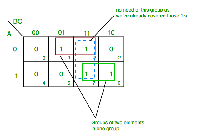
From red group we get product term—
A’C
From green group we get product term—
AB
Summing these product terms we get- Final expression (A’C+AB)
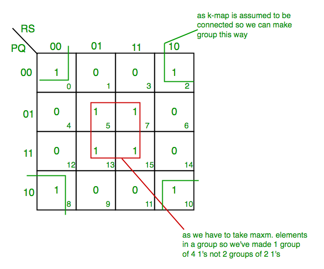
- K-map for 4 variables
F(P,Q,R,S)=∑(0,2,5,7,8,10,13,15)
From red group we get product term—
QS
From green group we get product term—
Q’S’
Summing these product terms we get- Final expression (QS+Q’S’)
POS FORM
- K-map of 3 variables-
F(A,B,C)=π(0,3,6,7)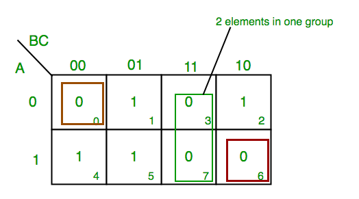
From red group we find terms
A B C’
Taking complement of these two
A’ B’ C
Now sum up them
(A’ + B’ + C)
From green group we find terms
B C
Taking complement of these two terms
B’ C’
Now sum up them
(B’+C’)
From brown group we find terms
A’ B’ C’
Taking complement of these two
A B C
Now sum up them
(A + B + C)
We will take product of these three terms :Final expression (A’ + B’ + C) (B’ + C’) (A + B + C)
2. K-map of 4 variables-
F(A,B,C,D)=π(3,5,7,8,10,11,12,13)

From green group we find terms
C’ D B
Taking their complement and summing them
(C+D’+B’)
From red group we find terms
C D A’
Taking their complement and summing them
(C’+D’+A)
From blue group we find terms
A C’ D’
Taking their complement and summing them
(A’+C+D)
From brown group we find terms
A B’ C
Taking their complement and summing them
(A’+B+C’)
Finally we express these as product –(C+D’+B’).(C’+D’+A).(A’+C+D).(A’+B+C’)
Minimization of Boolean Functions using K-Maps
If we consider the combination of inputs for which the Boolean function is ‘1’, then we will get the Boolean function, which is in standard sum of products form after simplifying the K-map.
Similarly, if we consider the combination of inputs for which the Boolean function is ‘0’, then we will get the Boolean function, which is in standard product of sums form after simplifying the K-map.
Follow these rules for simplifying K-maps in order to get standard sum of products form.
- Select the respective K-map based on the number of variables present in the Boolean function.
- If the Boolean function is given as sum of min terms form, then place the ones at respective min term cells in the K-map. If the Boolean function is given as sum of products form, then place the ones in all possible cells of K-map for which the given product terms are valid.
- Check for the possibilities of grouping maximum number of adjacent ones. It should be powers of two. Start from highest power of two and upto least power of two. Highest power is equal to the number of variables considered in K-map and least power is zero.
- Each grouping will give either a literal or one product term. It is known as prime implicant. The prime implicant is said to be essential prime implicant, if atleast single ‘1’ is not covered with any other groupings but only that grouping covers.
- Note down all the prime implicants and essential prime implicants. The simplified Boolean function contains all essential prime implicants and only the required prime implicants.
Note 1 − If outputs are not defined for some combination of inputs, then those output values will be represented with don’t care symbol ‘x’. That means, we can consider them as either ‘0’ or ‘1’.
Note 2 − If don’t care terms also present, then place don’t cares ‘x’ in the respective cells of K-map. Consider only the don’t cares ‘x’ that are helpful for grouping maximum number of adjacent ones. In those cases, treat the don’t care value as ‘1’.
Example
Let us simplify the following Boolean function, f= WX’Y’ + WY + W’YZ’ using K-map.
The given Boolean function is in sum of products form. It is having 4 variables W, X, Y & Z. So, we require 4 variable K-map. The 4 variable K-map with ones corresponding to the given product terms is shown in the following figure.
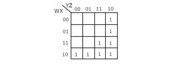
Here, 1s are placed in the following cells of K-map.
- The cells, which are common to the intersection of Row 4 and columns 1 & 2 are corresponding to the product term, WX’Y’.
- The cells, which are common to the intersection of Rows 3 & 4 and columns 3 & 4 are corresponding to the product term, WY.
- The cells, which are common to the intersection of Rows 1 & 2 and column 4 are corresponding to the product term, W’YZ’.
There are no possibilities of grouping either 16 adjacent ones or 8 adjacent ones. There are three possibilities of grouping 4 adjacent ones. After these three groupings, there is no single one left as ungrouped. So, we no need to check for grouping of 2 adjacent ones. The 4 variable K-map with these three groupings is shown in the following figure.
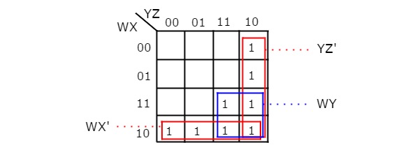
Here, we got three prime implicants WX’, WY & YZ’. All these prime implicants are essential because of following reasons.
- Two ones (m8 & m9) of fourth row grouping are not covered by any other groupings. Only fourth row grouping covers those two ones.
- Single one (m15) of square shape grouping is not covered by any other groupings. Only the square shape grouping covers that one.
- Two ones (m2 & m6) of fourth column grouping are not covered by any other groupings. Only fourth column grouping covers those two ones.
Therefore, the simplified Boolean function is
f = WX’ + WY + YZ’
Follow these rules for simplifying K-maps in order to get standard product of sums form.
- Select the respective K-map based on the number of variables present in the Boolean function.
- If the Boolean function is given as product of Max terms form, then place the zeroes at respective Max term cells in the K-map. If the Boolean function is given as product of sums form, then place the zeroes in all possible cells of K-map for which the given sum terms are valid.
- Check for the possibilities of grouping maximum number of adjacent zeroes. It should be powers of two. Start from highest power of two and upto least power of two. Highest power is equal to the number of variables considered in K-map and least power is zero.
- Each grouping will give either a literal or one sum term. It is known as prime implicant. The prime implicant is said to be essential prime implicant, if atleast single ‘0’ is not covered with any other groupings but only that grouping covers.
- Note down all the prime implicants and essential prime implicants. The simplified Boolean function contains all essential prime implicants and only the required prime implicants.
Note − If don’t care terms also present, then place don’t cares ‘x’ in the respective cells of K-map. Consider only the don’t cares ‘x’ that are helpful for grouping maximum number of adjacent zeroes. In those cases, treat the don’t care value as ‘0’.
Example
Let us simplify the following Boolean function, using K-map.
The given Boolean function is in product of Max terms form. It is having 3 variables X, Y & Z. So, we require 3 variable K-map. The given Max terms are M0, M1, M2 & M4. The 3 variable K-map with zeroes corresponding to the given Max terms is shown in the following figure.

There are no possibilities of grouping either 8 adjacent zeroes or 4 adjacent zeroes. There are three possibilities of grouping 2 adjacent zeroes. After these three groupings, there is no single zero left as ungrouped. The 3 variable K-map with these three groupings is shown in the following figure.
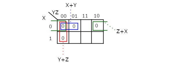
Here, we got three prime implicants X + Y, Y + Z & Z + X. All these prime implicants are essential because one zero in each grouping is not covered by any other groupings except with their individual groupings.
Therefore, the simplified Boolean function is
f = ..
In this way, we can easily simplify the Boolean functions up to 5 variables using K-map method. For more than 5 variables, it is difficult to simplify the functions using K-Maps. Because, the number of cells in K-map gets doubled by including a new variable.
Due to this checking and grouping of adjacent ones or adjacent zeros will be complicated. We will discuss Tabular method in next chapter to overcome the difficulties of K-map method.
Various Implicants in K-Map
Prerequisite – K – Map (Karnaugh Map)
Implicant is a product/minterm term in Sum of Products (SOP) or sum/maxterm term in Product of Sums (POS) of a Boolean function. E.g., consider a boolean function, F = AB + ABC + BC. Implicants are AB, ABC and BC.
Implicant is a product/minterm term in Sum of Products (SOP) or sum/maxterm term in Product of Sums (POS) of a Boolean function. E.g., consider a boolean function, F = AB + ABC + BC. Implicants are AB, ABC and BC.
- Prime Implicants –
A group of square or rectangle made up of bunch of adjacent minterms which is allowed by definition of K-Map are called prime implicants(PI) i.e. all possible groups formed in K-Map.
Example:
- Essential Prime Implicants –
These are those subcubes(groups) which cover atleast one minterm that can’t be covered by any other prime implicant. Essential prime implicants(EPI) are those prime implicants which always appear in final solution.
Example:
- Redundant Prime Implicants –
The prime implicants for which each of its minterm is covered by some essential prime implicant are redundant prime implicants(RPI). This prime implicant never appears in final solution.
Example:
- Selective Prime Implicants
The prime implicants for which are neither essential nor redundant prime implicants are called selective prime implicants(SPI). These are also known as non-essential prime implicants. They may appear in some solution or may not appear in some solution.
Example:
Example-1: Given F = ∑(1, 5, 6, 7, 11, 12, 13, 15), find number of implicant, PI, EPI, RPI and SPI.

No. of Implicants = 8
No. of Prime Implicants(PI) = 5
No. of Essential Prime Implicants(EPI) = 4
No. of Redundant Prime Implicants(RPI) = 1
No. of Selective Prime Implicants(SPI) = 0
Example-2: Given F = ∑(0, 1, 5, 8, 12, 13), find number of implicant, PI, EPI, RPI and SPI.

No. of Implicants = 6
No. of Prime Implicants(PI) = 6
No. of Essential Prime Implicants(EPI) = 0
No. of Redundant Prime Implicants(RPI) = 0
No. of Selective Prime Implicants(SPI) = 6
Example-3: Given F = ∑(0, 1, 5, 7, 15, 14, 10), find number of implicant, PI, EPI, RPI and SPI.

No. of Implicants = 7
No. of Prime Implicants(PI) = 6
No. of Essential Prime Implicants(EPI) = 2
No. of Redundant Prime Implicants(RPI) = 2
No. of Selective Prime Implicants(SPI) = 4
Example-4: GATE IT 2006 |
Thanks
No comments:
Post a Comment